B Series
Cable glands for hazardous area application
Refineries and Petrochemical Plants ·Chemical and Pharmaceutical Plants · Drilling for Gas and/or Petroleum · Gas Distribution Lines and Plants
Petrol Stations for Vehicles · Printing Industry · Varnishing Plants · Coal Mines · Waste Water Treatment Plants and Waste Management
Grain Storage · Wood Processing · Sugar Processing · Metalworking · Food Industry


Barrier Cable glands for unarmoured and wire armoured or braided, tape armoured, lead sheathed cables.
“B series” cable glands offer a wide variety of products, suitable to meet all customer needs.
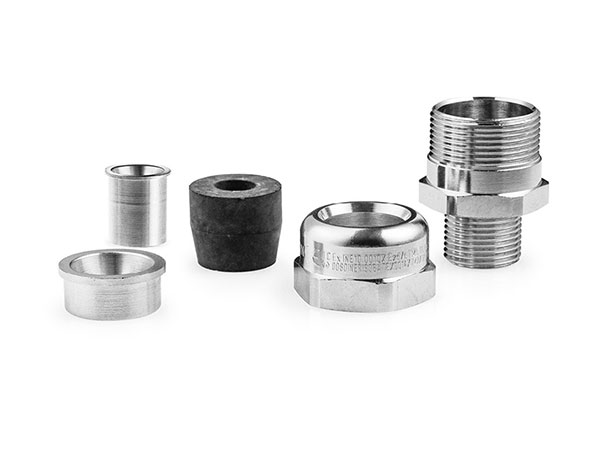
The cable glands are available in a standard version or with a male or female threaded backnut, the trumpet backnut perfect for mobile poses in which potential damages must be limited caused by repeated bending of the outgoing cable of the cable gland. Suitable versions for cables coated with lead sheathing are also available.
The container positioned inside the body of the cable gland aids the gathering of the epoxy resin for the resin treatment as required in some applications of the EN/IEC 60079-14 standard.
Two kinds of resin are available: a liquid and a solid, which may be used according to the needs of the client.
The material of the cable glands may be natural brass or nickel-plated brass, stainless steel AISI 316L and aluminium.
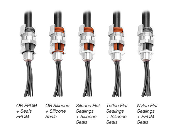
The interior washer may be EPDM or silicone; to be selected according to the operating ambient temperature, like the seal are available in nylon, silicone or PTFE or O-Rings available in EPDM or silicone.
The wide variety of available threads allows the user to choose the most suitable for their needs; this will limit the use of threaded adaptors to reduce the overall dimensions and application costs.
Features
01 Safety
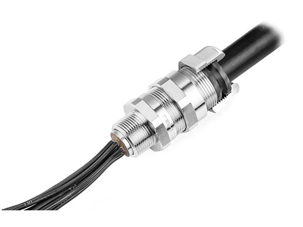
The rubber pad thanks to its particular design, clamps the external diameter of the cable for the entire height of the passage hole, ensuring the highest tensile seal and protecting the cable from any possible damage caused by different rubber pads, with its form which tightens the cable in only one point. This feature means that these cable glands do not require any additional clamping to the cable up to size 50.


02 Taylor-made
Possibility to choose between implementation of the body with OR or flat gasket, according to their needs and following material couplings in compliance with operating temperatures.
03 Integration
Container for resin integrated into the cable gland body and easily inspected.


04 Simplicity
Reduced number of components, which reduces the possibility of loosing some parts or incorrect assembly..
05 Design
External rubber pad which locks the outer sheath of the cable, providing protection against water and moisture.
ONLY FOR ARMOURED CABLE

Solid Compound
Preparation of epoxy resin - steps 01 to 04
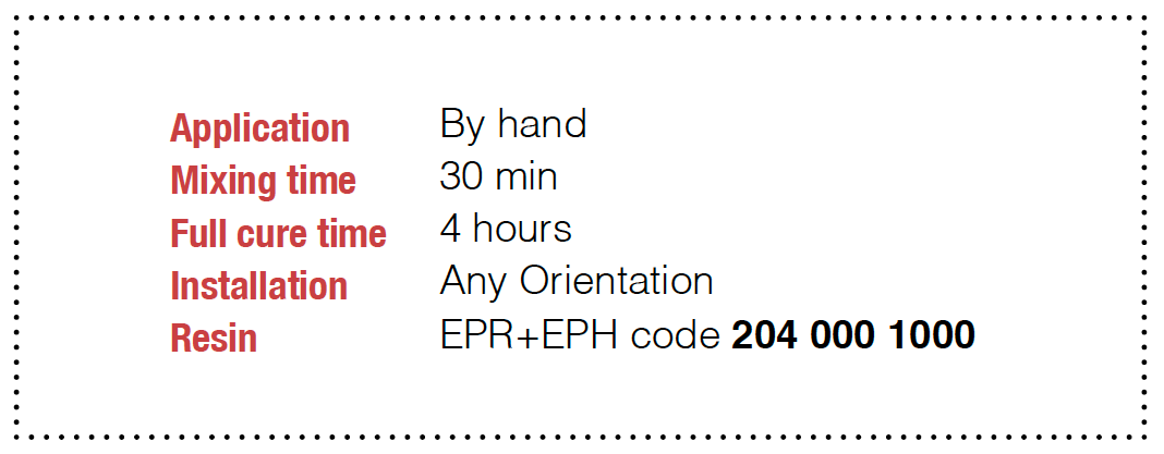
When using the compound, be sure to wear the gloves provided with the resin.
The epoxy resin is provided in a package with two separate parts. These must be mixed in a ratio of 1:1 until the compound is a single colour and without streaks.
The best solution for mixing the two parts is by rolling and bending the components several times together. Once mixed, the resin must be used within 30 minutes.
Over time it will begin to harden. The compound should not be stored at a temperature below 20°C before
being mixed. At lower temperatures, it will becomes difficult to mix. 3 to 4 hours are necessary at a temperature of between 20°C to 30°C so that the compound solidifies. They have to spend 12 to 24 hours at a temperature of between 20°C and 30°C until the compound reaches an optimal state.
If the compound comes in contact with one’s skin, it must be removed with a detergent and in no case allowed to harden.
Mix only enough compound to assemble one cable gland at a time.
The compound may be adversely affected by certain solvent fumes. If these fumes are present in the vicinity of the cable glands in service, specific precautions may be necessary. The compound polymerizes to a Shore hardness of 85. The compound, when completely set, is suitable to use at a range of service temperatures from -60°C to +130°C.
Note: Consider that the setting time may be longer when the room temperature is below 20°C.
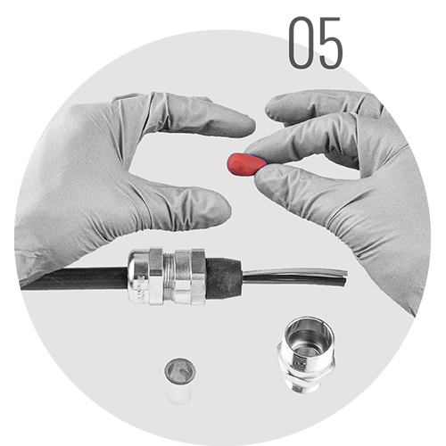
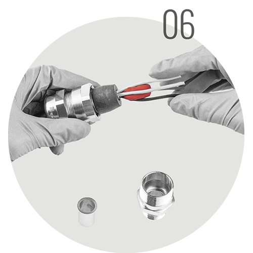
Application of the epoxy resin - steps 05 to 08
Prepare a resin cylinder to the required size 05.
Place it inside the cables as shown in figure 06.
Tighten the cables until they are in the resin and if necessary, add more resin to the outside so as to get a resin cylinder homogeneous with the cables inside 07.
Move together the container and the upper ring; be sure to get rid of any excess resin.
Then insert the container into the gland body and tighten the backnut to the body. Let it sit long enough for the resin to harden. Once the resin has polymerised, it will be possible to inspect the container and check the result 08.
KIT NEEDED TO SEAL 1 CABLE GLAND


MIX SET UP


APPLICATION


Liquid Compound NEW

N. CABLE GLANDS SEALED WITH 1 KIT COMPOUND
SET UP
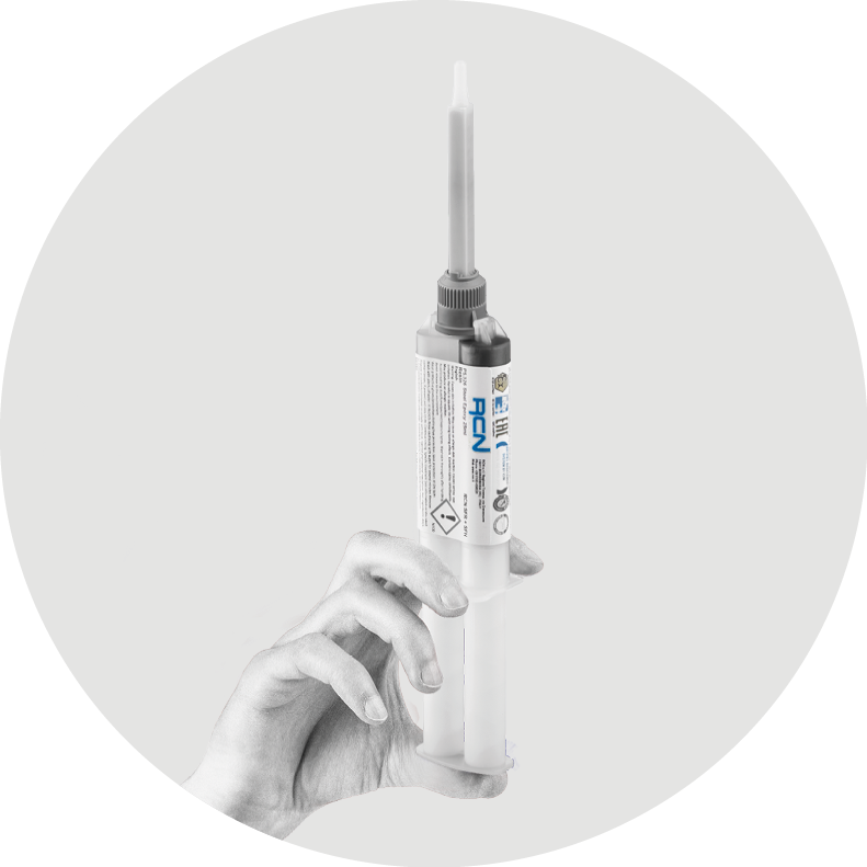
01 Bi-syringe can be reused, keep the cap.

02
SFR+SFH Resin - 25ml Syringe and Mixer (code 2040002000)

Mixer replacement for SFR+SFH Resin 2040002100

Reducer D. 1,6 mm mixer for SFR + SFH resin (code 2040002200)

KEEP ALWAYS VERTICAL
03

04
05

06

07
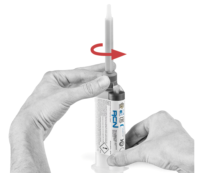
To fill small spaces between cables, add the Reducer D on top of the nozzle.

07b
Turn over the nozzle to insert the resin inside the cable gland. Hold in position for at least 24 h

HOW TO ORDER
Follow the numbers
Example code
Specific requirements for creator code
Additional specifications

0 Kit version
Includes cable glands and the requested complete series of the rubber seals accompanying the size. Each cable gland is equipped with extra indoor/outdoor
rubber pads for each size. The user may choose the rubber pad suitable for the cable diameter or opt for the kit version, which includes all the pads by size.

1 Type
RN | RNT | RAT | RNC | RNM | RAC | RAM | RAS | RAD | RATD | RALD
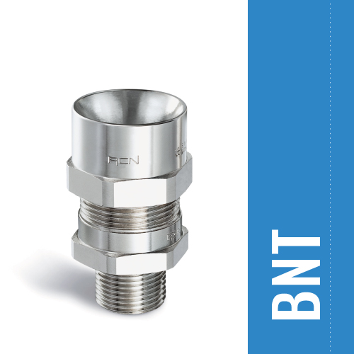
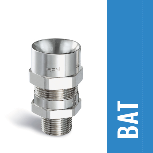
BN | BNT | BAT | BNC | BNM | BAC | BAM | BAS | BAD | BATD | BALD
SN | SNT | SAT | SNC | SNM | SAC | SAM | SAS | SAD | SATD | SALD
2 Size
16 | 20 | 25 | 32 | 40 | 50 | 63 | 75 | 90A | 90B
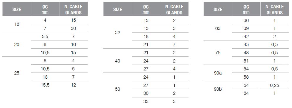
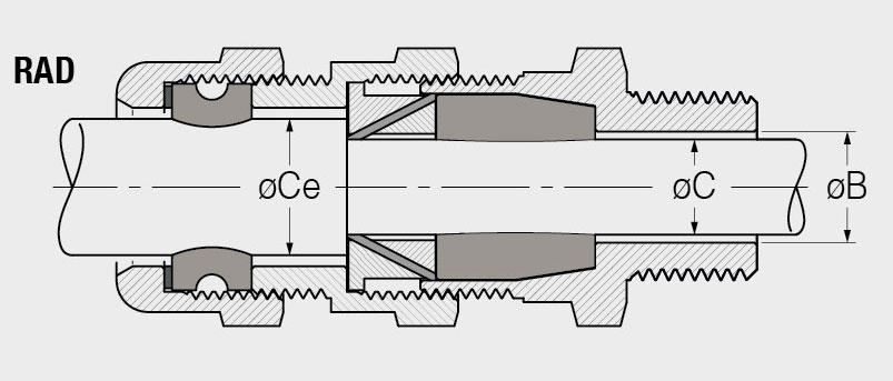
3 Ø C Max dimension
Inner seal dimension: choose the max size of the range to compose the code (see drawing and table on data sheet). For all cable glands.
Armoured or screened cables: under armour cable diameter.
Unarmoured cables: external cable diameter.
3E Ø Ce Max dimension
Outer seal dimension: choose the max size of the range to compose the code (see drawing and table on data sheet). Only for type: RAD RALD RATD - BAD BALD BATD and only for armoured or screened cables: external cable diameter.
4 Standard threads
4E & threads code
4 - For all cable glands
4E Only for type: RNC RNM RAC RAM - BNC BNM BAC BAM
5 Seals material code
EP
EPDM
SI
Silicone
6 Material code
OT | ON | S6 | AL | AVP
Brass | Nickel-plated brass | AISI 316L Stainless Steel | Aluminium | AVP steel
7 O-ring
Alternatively to the fl at gasket, in order to ensure the degree of IP protection, it is possible to request the “O-Ring version” cable gland.
For all cable glands, ISO metrical threads only

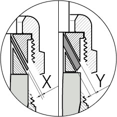
8 Reduced cone
The cable glands provided are standard and may not be used for braided, taped or wired armoured cables with thickness from 0 to 0.9 mm (X).
Upon request the cable glands can be provided suited for wire-armoured cables with thickness from 1 to 2.5 mm (Y). In this case add BS code.
Only for armoured cable:
RAT RAC RAM RAS RAD RATD RALD - BAT BAC BAM BAS BAD BATD BALD
3 Threads with dimensions less than usual standards the seals dimensional range is reduced.
3E Cable glands type RAD.20. with thread ISO M20 x 1,5 (or superior) the available seals are: 5,5 ÷ 8 • 8 ÷ 10,5 • 10,5 ÷ 13 5 ÷ 10 • 10 ÷ 15
Cable glands type RAD.20. with thread ISO M16 x 1,5 the available seals are: 5,5 ÷ 8 • 8 ÷ 10,5 5 ÷ 10 • 10 ÷ 15

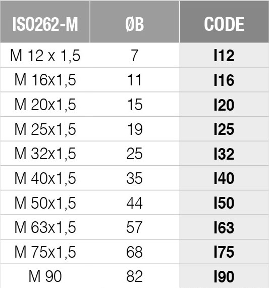
“Ø B” must be bigger than “Ø C” and “Ø Ce” See “Table of threads” below for “Ø B” dimension.

4 TABLE OF
4E THREADS