
Technical
1.1 Reference Standards
EC/EN 60079-0
Explosive atmospheres
Part 0: General requirements
IEC/EN 60079-1
Explosive atmospheres
Part 1: Equipment protection by flameproof enclosures «d»
IEC/EN 60079-7
Explosive atmospheres
Part 7: Equipment protection by increased safety «e»
IEC/EN 60079-15
Explosive atmospheres
Part 15: Equipment protection by type of protection «n»
IEC/EN 60079-31
Explosive atmospheres
Part 31: Equipment dust ignition protection by enclosure «t»
IEC/EN 62444 (previously EN 50262)
Metric cable glands for electrical installation
IEC/EN 60423
Conduits for electrical purposes.
Outside diameters of conduits for electrical installations and threads for conduits and fittings
IEC/EN 60529
Degree of protection provided by enclosures (IP Code)
Conformity to EU Directive 2011/65/EU (RoHS II directive)
The product range cable glands, fittings and accessories is produced in full compliance with the Directive 2011/65/EU “Restriction of the Use of Certain Hazardous Substances in Electrical and Electronic Equipment” (RoHS).

1.2 Certifications
Cable glands KT series
ATEX Certificate: INERIS 16 ATEX 0045X
Type examination certificate: INERIS 17 ATEX 3004 (Ex nR IIC Gc)
IECEx Certificate: IECEx INE 16.0054X
EAC Certificate: Ru C-IT.AЯ45.B.00909
CCC Ex NEPSI Certificate: Nr. 2021322313003710
Cable glands BX series
ATEX Certificate: CESI 14ATEX069X
IECEx Certificate: IECEx CES 15.0001X
EAC Certificate: Ru C-IT.AЯ45.B.00909
CCC Ex NEPSI Certificate: Nr. 2021322313003704
Cable glands R and B series
ATEX Certificate: INERIS 06 ATEX 0014X
Type examination certificate: INERIS 17 ATEX 3009X (Ex nR IIC Gc)
IECEx Certificate: INE 10.0010X
EAC Certificate: Ru C-IT.AЯ45.B.00909
CCC Ex NEPSI Certificate: Nr. 2021322313003706
Accessories A, M, N series and plugs T type
ATEX Certificate: INERIS 12 ATEX 0089X
IECEx Certificate: INE 10.0014X
EAC Certificate: Ru C-IT.AЯ45.B.00909
CCC Ex NEPSI Certificate: Nr. 2021322313003705
Product quality assurance notification
ATEX (QAN): INERIS 03 ATEX Q702
IECEx (QAR) FR/INE/QAR10.0003
Quality management system
In accordance to UNI EN ISO 9001:2015 standard
Certificate ICIM n. 1870
2.1 Correspondence between hazardous areas, substances and categories

The cable glands and accessories are made to be istalled in the following areas:
• Safe area: industrial execution
• Zone 1 and 2, Zone 21 and 22: Ex db / Ex eb / Ex tb execution
• Group I (mines), category M2 (I M2)
• Group II (surface), category 2, potentially explosive atmospheres of mixture of air gases, vapours, mists, or dusts (II 2 GD)
• Groups of gas IIA, IIB e IIC
• Groups of dusts: IIIA, IIIB e IIIC
The classification of areas, foresees that hazardous areas are divided into zones based on the frequency and duration of the occurrence of an explosive atmosphere and the type of hazardous substances (liquids, gases and vapours or dust).
For more information refers to the following standards
• IEC/EN 60079-10-1 Explosive atmospheres. Part 10-1: Classification of areas - Explosive gas atmospheres
• IEC/EN 60079-10-2 Explosive atmospheres. Part 10-2: Classification of areas - Combustible dust atmospheres
2.2 EPL Apparatus Electrical installations in hazardous area


For more information refers to the following standards
• IEC/EN 60079-14 Explosive atmospheres. Part 14: Electrical installations design, selection and erection
• IEC/EN 60079-17 Explosive atmospheres. Part 17: Electrical installations inspection and maintenance
2.3 EX Equipment

2.4 Gas and dusts temperature classes

2.5 Flameproof protection

3.1 IP degree of protection

4.1 Threads
TAPERED
Connection of Cables to Equipment. Cable glands with tapered threads shall not be used in enclosures having gland plates with unthreaded entries.

CYLINDRICAL


5.1 Seals & Products ambient temperature

5.2 Materials code

Cable glands - STANDARDS ABSTRACT
Cable gland is a mechanical device designed to connect and secure the cable to the equipment. Cable glands could be made in plastic, brass, aluminium and stainless steel.
The cable glands can be used with all types of electrical power, signal, telecommunications and optical fiber cables.
The cable glands, using the seals, the resin, the gaskets and the eventual sealing of the threads, provide protection against the entrance of liquids, gas and dust in equipment, ensuring the maintenance of the required IP degree of protection.
In addition, when they are used in hazardous areas, maintain the
Ex mode of protection of the machine to which they are connected.
Here below you can find the main requirements required by the standards, regarding the cable glands and accessories design, selection and erection.
6.1 CEI EN IEC 60079-0:2018 Explosive atmospheres
Part 0: Equipment- General requirements.
Identical to EN IEC 60079-0:2018
Cable glands
Cable glands, when installed in accordance with the instructions required, shall not invalidate the specific characteristics of the Type of Protection of the electrical equipment on which they are mounted.
This shall apply to the whole range of cables specified by the manufacturer of the cable glands as suitable far use with those glands. Cable glands may form an integral part of the equipment where one major element or part forms an inseparable part of the enclosure of the equipment. In such cases, the glands shall be tested with the equipment.
Non-threaded cable glands, for Group I, shall be:
• Ex Equipment Cable Glands;
• Ex Components; or included as part of the certificate for the complete equipment.
Non-threaded cable glands, for Group Il or Group III, shall be:
• Ex Components; or included as part of the certificate for the complete equipment.
Threaded cable glands and cable transit devices, for Group I, Group II, or Group III, shall be:
• Ex Equipment Cable Glands;
• Ex Components; or included as part of the certificate for the complete equipment.
Cable glands and cable transit devices, whether integrai or separate, shall meet the relevant requirements of Annex A.
Blanking elements
Blanking elements, intended to close unused openings in the enclosure walls of electrical equipment, shall satisfy the
requirements of the specific Type of Protection concerned.
The blanking element shall only be removable with the aid of a tool.
Threaded blanking elements shall be Ex Equipment Blanking Elements, Ex Components, or included as part of the certificate for the complete equipment.
Non-threaded blanking elements, for Group I, shall be Ex Equipment Blanking Elements, Ex Components, or included as part of the certificate for the complete equipment.
Non-threaded blanking elements, for Group Il or Group lii, shall be Ex Components or included as part of the certificate for the complete equipment.
Thread adapters
Thread adapters shall satisfy the requirements of the specific Type of Protection concerned.
Thread adapters shall be Ex Thread Adapters, Ex Components, or included as part of the certificate for the complete equipment.
Ex marking for explosive gas atmospheres
Ex Equipment cable glands, Ex Equipment blanking elements, and Ex Equipment thread adapters need not be marked with a temperature class or maximum surface temperature in degrees Celsius.
IP rating (degree of protection)
Cable glands, when installed in accordance with the instructions provided by the manufacturer, shall be capable to guarantee the same IP rating as required for the enclosure.
Test for degree of protection (IP) of cable glands
The test shall be carried out in accordance with IEC 60529, using one cable-sealing ring of each of the different permitted sizes for each type of cable gland.
• Group I & group II: – IP54 Minimum
• Group III, EPL Da, EPL Db & EPL Dc– IP6X minimum
Marking of cable-sealing rings
The cable-sealing rings for cable glands that permit a variety of ring sizes shall be marked with the minimum and maximum diameters (mm) of the permitted cables.
Cable-sealing rings shall be identified in order to show if the ring is appropriate for the cable gland.
Where the gland and the ring are intended to be used at temperatures outside the range –20 °C to +75 °C, they shall be marked with the temperature range.
The specific details of identification for sealing rings and temperature ranges is detailed in the instructions.
6.2 CEI EN 60079-1:2016 Explosive atmospheres
Explosive atmospheres. Part 1: Equipment protection by flameproof enclosures “d”
Identical to EN 60079-1:2014 and IEC 60079-1:2014
Ex equipment blanking element
Threaded blanking elements for Group I or II, and non-threaded blanking elements for Group I, that
– are intended to close unused entries,
– are tested separately from the equipment enclosure,
– have an equipment certificate, and
– are intended to be fitted to the equipment enclosure without further consideration.
Ex equipment thread adapter
Thread adapter tested separately from the enclosure but having an equipment certificate and which is intended to be fitted to the equipment enclosure without further consideration.
General requirements of Ex d cable glands
In the instructions shall detail specific that the flameproof joints are not intended to be repaired. The surface of joints may be protected against corrosion.
Threaded joints
Joints shall comply with the requirements given below (as required by the standard)
Cylindrical threaded joints
Pitch ≥ 0,7 mm
Thread form and quality of fit:
Medium or fine tolerance quality (ISO 965-1 and ISO 965-3b)Threads engaged ≥ 5
Depth of engagement
Volume ≤ 100 cm3 ≥ 5 mm
Volume >100 cm3 ≥ 8 mm
Where the pitch exceeds 2 mm, special manufacturing precautions may be necessary (for example, more threads engaged) to ensure that the electrical equipment can pass the test for non-transmission of an internal ignition.
Entries for Ex d enclosures
The flameproof properties of the enclosure are not altered if all entries meet tone of the following requirements:
• internal metric threads with a tolerance class of 6H or better according to ISO 965-1 and ISO 965-3, and any chamfer or undercut is limited to a maximum depth of 2 mm from the external wall surface;
• external metric threads with a threaded part of at least 8 mm in length and at least eight full threads. If the thread is provided with an undercut, then a non-detachable and non-compressible washer or equivalent device shall be fitted to ensure the required length of thread engagement;
Cable glands
Cable glands, whether integral or separate, shall meet the specific requirements of the standard (annex C) and create, on the enclosure, the joint widths and gaps required (clause 5).
Conduit sealing devices
Conduit sealing devices, whether integral or separate, shall meet the requirements of the standard (annex C) and create, on the enclosure, the joint widths and gaps required (clause 5).
Conduit entries are permitted only for electrical equipment of Group II.
A sealing device such as a stopping box with setting compound shall be provided, either as part of the flameproof enclosure or immediately at the entrance thereto.
The distance from the face of the seal closest to the enclosure (or intended end-use enclosure), and the outside wall of the enclosure (or intended end-use enclosure) shall be as small as practical.
Blanking elements
If, at the determination of the manufacturer, entries provided in a flameproof enclosure are not intended to always be used, they shall be closed by Ex equipment or Ex component blanking elements so that the flameproof properties of the enclosure are maintained.
A blanking element shall not be used with a thread adapter.
6.3 CEI EN 60079-14:2015 Explosive atmosphere
Part 14: Electrical installations design, selection and erection.
Identical to EN 60079-14:2014 and IEC 60079-14:2013
Cables for fixed installations
Cables used for fixed installations in hazardous areas shall be appropriate for the ambient conditions in service.
Cables shall be sheathed with thermoplastic, thermosetting, or elastomeric material. They shall be circular and compact. Any bedding or sheath shall be extruded. Fillers, if any, shall be nonhygroscopic.
Selection of cable glands
Cable gland shall be selected to match the cable diameter. The use of sealing tape, heat shrink tube or other materials is not permitted to make the cable fit to the cable gland.
To meet the IP rating it may also be necessary to seal between cable glands, adapters and blanking elements and the enclosure by means of a sealing washer or thread sealant.
Connections of cables to equipment
Cable glands shall be installed in a manner that after installation they are only capable of being released or dismantled by means of a tool.
lf additional clamping is required to prevent pulling and twisting of the cable transmitting the forces to the conductor terminations inside the enclosure, a clamp shall be provided, as close as practicable to the gland along the cable.
Unused openings
Unused entries in the enclosure shall be sealed by blanking elements that maintain the degree of ingress protection lP54 or that required by the location, whichever is the higher. Blanking elements shall be of a type that can only be removed with the use of a tool.
For flameproof enclosures adapters shall not be used together with blanking elements.
Additional requirements for type of protection “d”- Flameproof enclosures
General
lf an Ex “d” gland clamping by the sealing ring (compression) is used with braided or armoured cable, it shall be of the type where the braid or armour is terminated in the gland and compression takes piace on the inner cable sheath.
For fine braided cable, where the braid is less than 0,15 mm diameter and has coverage of at least 70 % compression only on the outer sheath is accepted. Flameproof cable glands, adapters or blanking elements, having parallel threads may be fitted with a sealing washer between the entry device and the flameproof enclosure provided that, after the washer has been fitted, the applicable thread engagement is still achieved. (at least 5 full threads).
Suitable grease may be used provided it is non setting, non-metallic and non-combustible and any earthing between the two is maintained.
Selection of cable glands
The cable entry system shall comply with one of the following:
A
Cable glands sealed with setting compound (barrier cable glands) in compliance with IEC 60079-1 and certified as equipment;
B
Cables and glands meeting all of the following:
• cable glands comply with IEC 60079-1 and are certified as equipment
• cables used comply with requirements for cables for fixed installation (see 9.3.2)
• the connected cable is at least 3 m in length;
C
Indirect cable entry using combination of flameproof enclosure Ex d with a bushing and increased safety terminal box Ex e;
D
Mineral-insulated metal-sheathed cable with or without plastic outer covering with appropriate flameproof cable gland complying with IEC 60079-1;
E
Flameproof sealing device (for example a sealing chamber) specified in the equipment documentation or complying with IEC 60079-1 and employing a cable gland appropriate to the cables used.
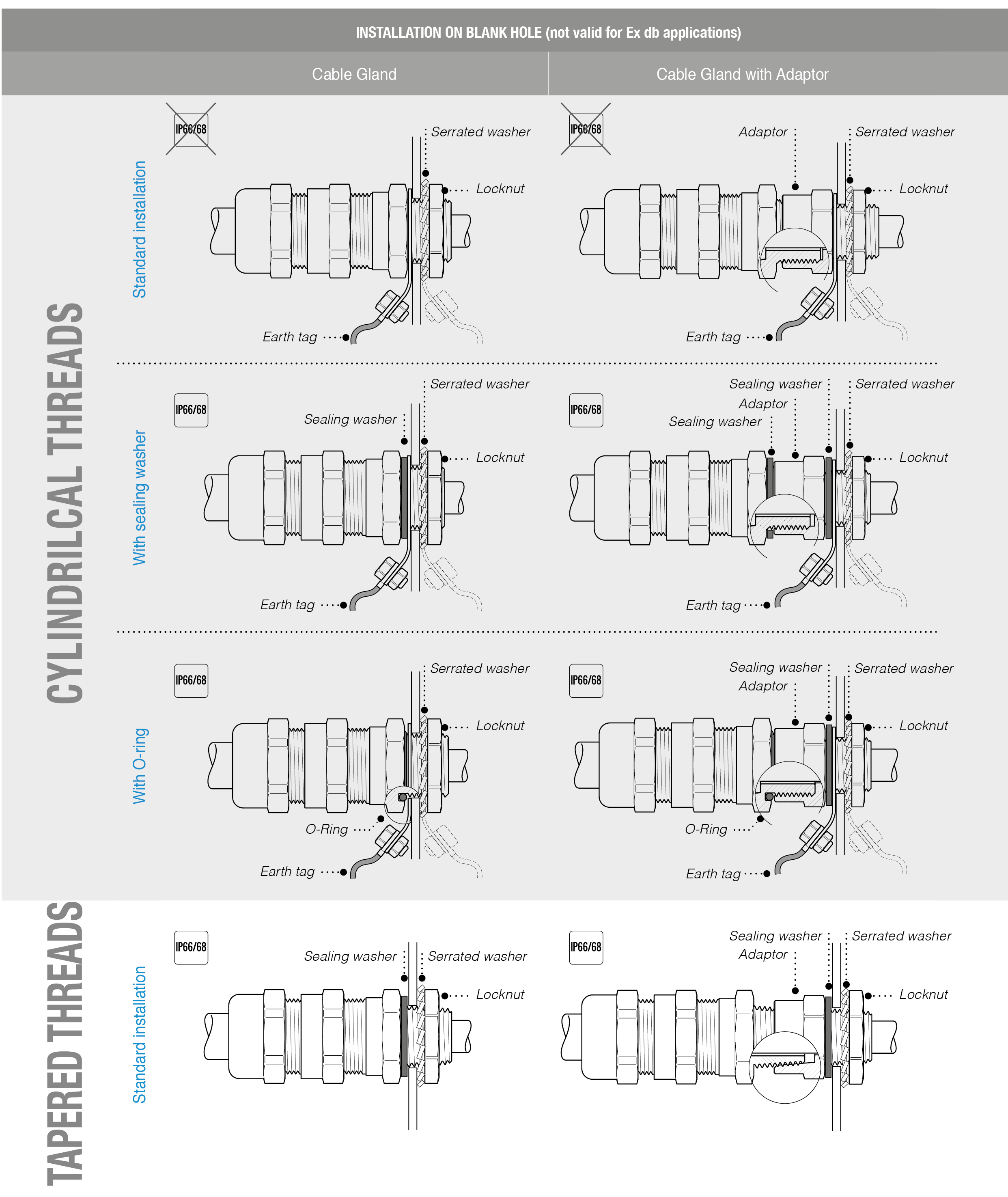
6.4 INSTALLATION GUIDE

6.5 Cable Glands - MARKINGS
The markings on cable glands, adaptors or plugs are very important as they allow the user to identify the article and manufacturer. Via the information on the markings, it is possible to check if the product meets the required application. Particular attention should be paid to certifications, relevant identification numbers, levels of protection and degree of protection IP.
The marking includes: name of the manufacturer or its trademark, manufacturer article identification number, certification issuer’s name or marking and certificate reference. If it is necessary to indicate specific conditions of use, an “”X”” shall be placed after the certificate reference. A specific Ex marking shall be used for explosive gases and/or dust atmospheres.
Ex cable glands, blanking elements and thread adaptors need not be marked with a temperature class or maximum surface temperature.

